Saddle System
Benefits of Acoustic Saddle Systems
Advantages
Applications
In suitable overall floor and ceiling constructions the Saddle System can be suitable for use in the following applications:
For applications with loading greater than a UDL of 1.5kN/m2 and Concentrated load of 1.4kN please contact CMS Danskin for advice about board capacity and recommended component centres.

Performance
In FFT2 Robust Detail testing the Saddle System achieved a performance of Delta Lw 22dB using the minimum permissible height.
Performance datasheets are available on request showing sound test information for the saddle system in conjunction with different structural floor and ceiling combinations.

Specification
The basic system height without packing should be able to fit between the high point in the subfloor and the desired Finished Floor Level (FFL). Packers and, where necessary, elevating blocks are then used to level out areas below the high point.
To calculate the basic system height determine the size of the void needed beneath the floor boarding by considering the height of services which will run in the void. Remember that service pipes may need space to cross over each other and that in the worst case this could occur at the high point of the tolerance in the subfloor. Add the thickness of the preferred floor boarding to give the basic system height. (N.B. If the floor is to comply
with Robust Details the void allowed must be at least 50mm.)
Double check that the basic system height at the high point will marry in with other fixed points in the building such as stairs, corridor screed levels or the thresholds of patio doors.
From the table below select the basic system height and floor boarding closest to (but not more than) your needs. Packing will make up any difference.
The above table is based on a Uniformly distributed load of 1.5kN/m2 and Concentrated load of 1.4kN as specified for self contained, single family dwelling units in BS6399-1:1996. Exceptional loads (such as storage heaters) may require support direct from the subfloor. It is also recommended that in high load areas such as kitchens and bathrooms support bearer centres are reduced to 300mm. Communal areas in blocks of flats such as corridors and vestibules will require special consideration. CMS Danskin can provide centres for other floor boarding and types of use.

Important Features
Due to their spanning function timber support bearers must be strength graded at the finished size – not just cut from larger graded sections. (Timber Research and Development Association guidance) All Saddle system softwood bearers are C16 strength graded and FSC certified. Laminated softwood with defined strength capabilities is used for sections where support bearer sizes fall below grading limits.
To properly support flooring boards the WPIF Code of Practice for Particleboard Flooring requires a minimum support bearer width of 45mm ( finished size ). All CMS Danskin Acoustics`Support Bearers are at least 45mm wide ( finished size ).
Saddles
The plastic in the injection moulded components in the Saddle System is manufactured from 100% recycled post production waste. The sources are consistent and of high quality. Saddles are manufactured from ABS and end of product life ABS is capable of being recycled.
Resilient Layer
The resilient layer on CMS Danskin Acoustic`s Saddles has a zero Global Warming Potential (GWP) and Zero Ozone Depletion Potential (ODP). The material is capable of being recycled.
Support Bearers
The Support Bearers in the Saddle System are sourced from sustainable well managed forests. They are FSC certified as standard with PEFC available on request.
Standard Saddle System
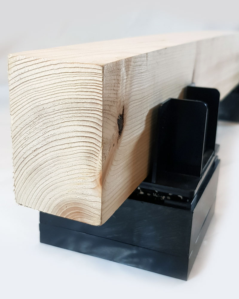
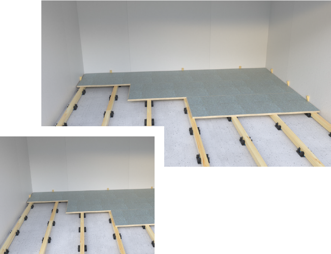
The Standard Saddle System uses structural flooring boards, C16 strength graded timber Support Bearers and Saddles with an integral acoustic resilient layer to construct a floating floor on top of a base floor. This basic system without packing should be able to fit between the highest point of the base floor and the desired finished floor level. Packers and, where necessary Elevating Blocks, are then used to level out areas below the high point. Flanking strips are used to prevent sound passing into the structure at the perimeter of the floor.
- Structural Flooring Overlay
- Packers (as required)
- Elevating Blocks (as required)
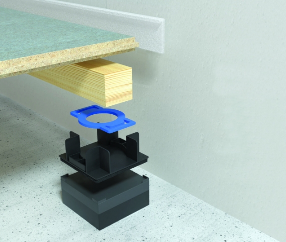
- Flanking Strip
- Support Bearer
(strength graded) - Saddle
(with resilient layer)
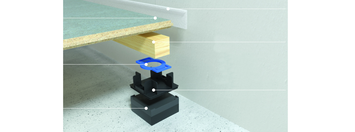
Standard Saddle System
Saddle systems can be designed using the following stock components:
- Small (8mm x 97mm x 97mm with 19mm upstands)
- Medium (8mm x 97mm x 97mm with 33mm upstands)
- Large (8mm x 97mm x 97mm with 55mm adapted upstands)
- 2mm, 3mm & 5mm packers
- 15mm & 30mm Elevating Blocks
- Laminated Softwood (LVL) 22mm x 45mm x 2400mm
- C16 Strength Graded Softwood 37mm x 47mm x 2400mm
- C16 Strength Graded Softwood 45mm x 45mm x 2400mm
- C16 Strength Graded Softwood 61mm x 45mm x 2400mm
- 18mm chipboard 2400mm x 600mm T&G4
- 22mm chipboard 2400mm x 600mm T&G4
- 18mm Engineered Ply 2400mm x 600mm T&G4
- 22mm Engineered Ply 2400mm x 600mm T&G4
- 18mm Smartspan 1200mm x 600mm T&G4
- 25mm Smartspan 1200mm x 600mm T&G4
- 28mm Smartspan 1200mm x 600mm T&G4
- 6mm ‘L’ Shaped Flanking Strip (1800mm lengths)
Height Ranges
The table below sets out the range of floor void depths which can be achieved using different Support Bearers in the Saddle System. To calculate the full height of the system please add the thickness of the preferred floor boarding.
Floor Void (Base floor to top of bearer in mm.)
- 30
- 35
- 40
- 45
- 50
- 55
- 60
- 65
- 70
- 75
- 80
- 85
- 90
- 95 to 200 mm
- (1)8mm Small saddle + 22mm laminated timber
14mm maximum packing - (2)8mm Medium saddle + 37mm timber
28mm maximum packing in 8mm elevation - (3)8mm Medium saddle + 45mm timber
28mm maximum packing in 8mm elevation - (4)8mm Medium saddle + 61mm timber
28mm maximum packing in 8mm elevation
- (1)30 to 44mm
- (2)45 to 73mm
- (3)53 to 81mm
- (4)69 to 97mm
Note 1: The use of packers and elevating blocks can increase the void height of the standard Saddle
Acoustic Saddle Systems
For each standard Support Bearer size the maximum centres at which Support Bearers and Saddles can be spaced are set out below. This information must be read in combination with any specific project guidance and the detailed installation guidelines. The centres are applicable to any of the following load conditions as defined by NA BS to EN 1991-1-1 UK National Annex to Eurocode 1, Part 1-1: General Actions – Densities, self-weight, imposed loads for buildings:
- A1 : Self contained dwellings / Student accommodation
- A3 : Bedrooms in hotels and motels
- A6 : Communal Areas in blocks of flats
Support Bearer – CMS Danskin Laminated Softwood LVL
22mm high x 45mm x 2400mm
| FLooring Board Type | Maximum Bearer Centres ( mm) | Maximum Saddle Centres ( mm) |
|---|---|---|
| 18mm chipboard T&G4 | 400 | 400 |
| 22mm chipboard T&G4 | 400 | 400 |
| 18mm Engineered Plywood T&G4 | 400 | 400 |
| 22mm Engineered Plywood T&G4 | 400 | 400 |
| 18mm Smartspan | 400 | 400 |
| 25mm Smartspan | 400 | 400 |
Support Bearer – Scandinavian softwood Kiln dried C16 37mm high x 47mm x 1800mm
| FLooring Board Type | Maximum Bearer Centres (mm) | Maximum Saddle Centres (mm) |
|---|---|---|
| 18mm chipboard T&G4 | 400 | 450 |
| 22mm chipboard T&G4 | 600 | 450 |
| 18mm Engineered Plywood T&G4 | 400 | 450 |
| 22mm Engineered Plywood T&G4 | 600 | 450 |
| 18mm Smartspan | 400 | 450 |
| 25mm Smartspan | 600 | 450 |
- UDL 1.5kN/m2, Concentrated Load 2.0 kN
- UDL 2.0kN/m2, Concentrated Load 2.0 kN
- UDL 3.0 kN/m2, Concentrated Load 2.0 kN
Support Bearer – Scandinavian Softwood Kiln Dried C16 45mm high x 45mm x 2400mm
| FLooring Board Type | Maximum Bearer Centres ( mm) | Maximum Bearer Centres ( mm) |
|---|---|---|
| 18mm chipboard T&G4 | 400 | 600 |
| 22mm chipboard T&G4 | 600 | 600 |
| 18mm Engineered Plywood T&G4 | 400 | 600 |
| 22mm Engineered Plywood T&G4 | 600 | 600 |
| 18mm Smartspan | 400 | 600 |
| 25mm Smartspan | 600 | 600 |
Support Bearer – Scandinavian Softwood Kiln Dried C16 61mm high x 45mm x 2400mm
| FLooring Board Type | Maximum Bearer Centres (mm) | Maximum Saddle Centres (mm) |
|---|---|---|
| 18mm chipboard T&G4 | 400 | 600 |
| 22mm chipboard T&G4 | 600 | 600 |
| 18mm Engineered Plywood T&G4 | 400 | 600 |
| 22mm Engineered Plywood T&G4 | 600 | 600 |
| 18mm Smartspan | 400 | 600 |
| 25mm Smartspan | 600 | 600 |
Extract from Structural Engineer`s report: PM Law Design report reference 184-1901 November 2019
Acoustic Performance
The sound insulation of party floors is a necessary requirement of the Building Regulations. Methods of satisfying the Regulations are set out in Approved Document E in England & Wales, Section 5 of the Technical Handbook in Scotland and Technical Booklet G in Northern Ireland. The CMS Danskin Acoustics Saddle System contributes significantly to the reduction of impact and airborne sound through party floors. When used with appropriate structural floor and ceiling constructions it has been demonstrated to meet the performance standards of the Building Regulations in Pre Completion testing.
The Saddle System also qualifies for use as an FFT2 floor in Robust Details and Scottish Example constructions. Details of the minimum performance requirements and laboratory test results for these schemes are given below.
| Design Approach | Performance Requirement | Laboratory Tested Performance |
|---|---|---|
| England & Wales Robust Detail Constructions (Note 1) | ||
| E-FC-1, E-FC-2, E-FC-7, E-FS-1, | FFT2 Floor void to be at least 50mm high (compressed) with 10mm (min.) void below Support Bearer Minimum rdDelta Lw 17dB | Saddle System with 55mm void rdDelta Lw 23dB |
| Scottish Robust Detail Constructions | ||
| V-FS-1 Steel/Concrete Composite | FFT2 2 Floor void to be at least 50mm high (compressed) with 10mm (min.) void below Support Bearer Minimum rdDelta Lw 17dB | Saddle System with 55mm void rdDelta Lw 23dB |
| Scottish Example Constructions | ||
| Floor Type 1B - Insitu concrete slab with FFT Floor Type 2B - Precast concrete slab with FFT | FFT2 2 Floor void to be at least 50mm high (compressed) with 10mm (min.) void below Support Bearer Minimum rdDelta Lw 17dB | Saddle System with 55mm void rdDelta Lw 23dB |
Notes:
- 1) In Northern Ireland these constructions are accepted as an alternative to PCT to demonstrate compliance with Part G (NI) for new dwellings.
- 2) Where a 10mm clearance is required for FFT compliance a 2mm packer is placed in each Saddle.
Dual
Height Saddle
The medium saddle has a raised plinth which can support timber in a higher position.
Rotating the saddle by 90˚ can provide 8mm of additional elevation or avoid the need for taller timber.
Pedestal Saddles
For floor voids above 200mm
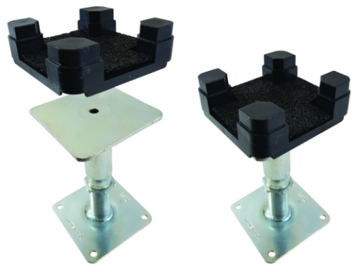
For floor voids above 200 mm Pedestal Saddles are a hybrid of the highly successful Saddle system and the proven technology of raised access flooring systems, blending together the components to achieve deeper floor systems with acoustic properties.
CMS Danskin Acoustics have adapted a steel raised access floor pedestal and developed an injection moulded headcap with an integral 3mm resilient layer on the upper surface which clips on top. This creates an acoustic flooring system capable of providing deeper voids with useful space.
The raised access floor pedestals are bonded to a clean, dry and dust free concrete substrate in the normal way using a one part, solvent free adhesive, and where appropriate, mechanical fixings.
The acoustic headcaps are clipped on top and standard C16 Support Bearers and packers are then used in the same way as in the standard Saddle System. Flooring boards are fitted to the top of Support Bearers.
Pedestal Range
| Pedestal Reference | Height Adjustment (mm) |
|---|---|
| H4 Ped | 110/185 |
| H4E Ped | 135/210 |
| H5 Ped | 150/225 |
| H5E Ped | 185/260 |
| H6 Ped | 200/275 |
| H6E Ped | 235/310 |
| H7 Ped | 250/325 |
| H8 Ped | 300/375 |
| H9 Ped | 350/425 |
| H10 Ped | 400/475 |
| X11 | 450/525 |
| X12 | 500/575 |
| X13 | 550/625 |
| X14 | 600/675 |
| X15 | 650/725 |
| X16 | 700/775 |
| X17 | 750/825 |
| X18 | 800/875 |
| X19 | 850/925 |
| X20 | 900/975 |
Accessories
Pedestal Adhesive – 9kg (Coverage – approx. 150 peds) Saddle Headcap c/w resilient layer
Notes:
Standard pedestals over 300mm high must be adhesive bonded and mechanically fixed. HD pedestals over 500mm high require cross bracing. Higher elevations available on request.
Acoustic performance
Small sample test on ISO 10140-8 Heavyweight
Standard Floor
| Small sample test on ISO 10140-8 Heavyweight Standard Floor | |
|---|---|
| Delta Lw | 19dB |
Thermal Saddles
Optimal integration with underfloor heating
Underfloor heating pipes can be accommodated in the service zone provided by a standard Small or Medium Saddle. Typically warm water heating pipes are clipped to or inserted in insulation boards which are loose laid between the rows of Saddles and Support Bearers on top of the base floor.
However CMS Danskin Acoustics can also offer an adapted version of the Saddle System which can enhance the efficiency of these systems by elevating the insulation and pipes closer to the underside of the flooring panel. The patented shape of the Large Saddle also reduces gaps in the insulation coverage thereby reducing heat loss.
In most cradles the shape of the corner upstands prevent a snug fit between insulation boards and the support bearers, causing gaps between the insulation and the sides of the Support Bearers. The unique design of the Large Saddle means that these gaps are largely eliminated.
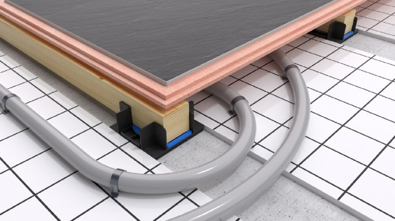
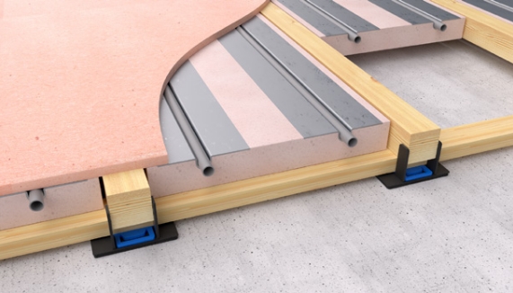
A system of counterbattens positioned within the Thermal Saddle means that underfloor heating insulation panels can be fully supported during installation and over the lifetime of the floor.
Previously clips have been placed on top of Support Bearers to hold the pipework and insulation panels against the underside of the flooring boards. However these clips often provide insufficient support when loops of pipework are pushed into place during installation, causing sag and introduction of inefficient air gaps.
To alleviate this, Large Thermal Saddles are used to allow the insulation and pipework to be supported with counter battens if required.
Dimensions
Please note the pictoral example of the counterbatten system is only one configuration. Many factors will determine the size of support bearers and counterbatten to be used, including floor depth, position and thickness of any insulation panel. For further advice please contact CMS Danskin Acoustics Technical.
Acoustic Performance
The Large Thermal Saddle uses the same resilient layer as other Standard Saddles; Please refer to Acoustic Performance table.
Smartspan Flooring
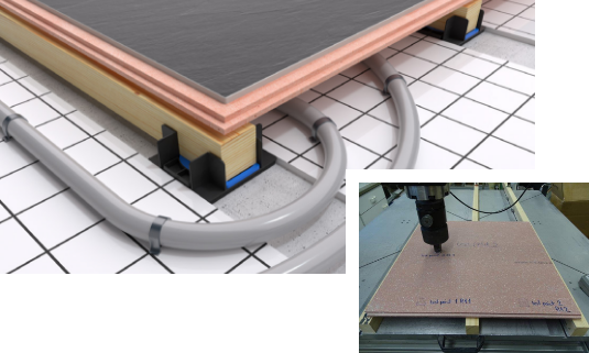
Enhanced thermal conductivity and stiffness for the Saddle System.
Smartspan is a calcium sulphate board which can span between the timber support bearers of the Saddle System with minimal deflection, making it an ideal substrate for stone and tiled finishes.
With a thermal conductivity of 0.44W/mK the Smartspan flooring panel is much more responsive to changes in underfloor heating settings than a standard chipboard panel.
Accessories
`L` Shaped Flanking Strip
6mm thick ,preformed `L` shaped acoustic foam supplied in strips 1.8m long packed in bags containing 100m. The innovative `L` shape makes it easy to fit and one size fits all floors. It is lightly trapped between the bottom of the skirting and the flooring board with the excess neatly trimmed off.
Flooring
18mm or 22mm Type P5 Moisture Resistant Grade , CE marked chipboard to BS EN 312 : Part 5. Alternatively WBP Spruce Plywood , CE marked and manufactured to BS 5268-2:2002.All panels are tongued and grooved on all four edges and supplied in sheet size 2400 x 600mm Peel off layers and protective coatings for chipboard are available.
CMS Danskin Support Bearers
Softwood Support Bearers are placed within the Saddles to support flooring panels. They are 45mm wide and generally supplied in 1800mm and 2400mm lengths for ease of handling.
The 1800 is available in 37mm and the 2400mm avilable is ,45mm , 52mm and 61mm heights as standard. In accordance with the recommendations of TRADA , Support Bearers are supplied in C16 stength graded timber. They are FSC certified as standard.
Colour Coded Packers
Packing is provided by means of innovative self locating plastic packers which are made in 2,3 and 5 thicknesses. The unique , patented packers achieve the levelling of uneven subfloors.
CMS Danskin Acoustic Saddles
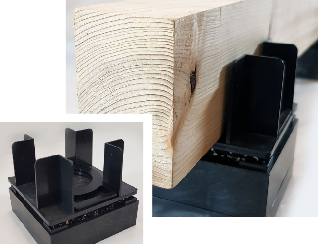
Saddles are 97mm x 97mm square and have a tough , injection moulded plastic headcap adhered to a high performance, recycled foam resilient layer.The headcap holds the Support Bearers to which flooring panels are fixed. The Saddles are available in three headcap heights (small, medium and large). The small Saddle permits 14mm of packing, the medium – 29mm and the large – 40mm. The different headcap heights maximise the packing of the appropriate Support Bearer. Each headcap has two small holes in the surface to lock packing pieces in place.The ingenious design of the headcap means that it can also support cross noggins for access panels or perimeter bearers. The standard height of the Saddle with the resilient layer attached is 11mm.
Elevating Block (Optional)
Elevating blocks are made from injection moulded plastic and they can be placed in combination below saddles where floor variations are extreme up to a maximum height of 150mm. They interlock with the Saddles and with each other and extend the height of systems to cope with major deviations in levels.The blocks come in 15mm and 30mm thicknesses.As the resilient layer remains on the base of the saddle in use , the overall acoustic performance is not impaired. Elevating blocks can also be used to raise the system to allow services to run in both directions under Support Bearers.
Features and benefits
Ideal substrate for large format and stone tiles. High thermal conductivity maximises energy efficiency.
Makes room temperature control more responsive. High density assists with reduction of sound transmission. Excellent fire rating. Dry solution enhances on site efficiency.
Acoustic Performance
The high density of the board also enhances the acoustic performance of the Saddle System. In an independent test conducted by the Building Research Establishment ( BRE ) 25mm Smartspan laid on the Standard Saddle system on top of a standard heavyweight concrete floor achieved an impact performance of Delta Lw 24dB.
Physical Characteristics
- Panel size: 1200 x 600mm
- Thicknesses: 18 , 25 , 28 & 32mm
- Edge detail: T&G – 4 sides
- Density: 1500 kg /m3
- Fire rating: Class A1 non combustible to EN 13501-1
Design Considerations
Base Floor
The building must be weatherproof and completely dried out before commencing installation of flooring systems.
Partitions
Load bearing partitions should not be built on top of a floating floor. For best acoustic performance it is preferred that non-loadbearing partitions are built from the subfloor but where lightweight non-loadbearing partitions are built on top of the floating floor a double row of Acoustic Bearers or Support Bearers should be placed directly below. In joisted subfloors, if the line of a partition does not fall above a structural joist then a ladder frame of bearers should be created.
Moisture
Where floating floors are used over a new in-situ concrete slab construction (with or without a screed) , a DPM should be positioned over the slab or screed to protect the floating floor from moisture. Where a pre-cast concrete floor has a relative humidity in excess of 75% when tested according to Annex A of BS 8201 a DPM should be placed over the base floor surface before laying the floating floor.
Communal Areas in Flats
It should be noted that the UK Annex to Eurocode 1 requires a higher load condition be considered for Communal Areas in blocks of flats. Please refer to “Actions on Structures, Part1-1 : General Actions, self weight, imposed loads for buildings“ – in particular tables NA.2 and NA.3. CMS Danskin Acoustics can provide assistance on suitable System components and centres for higher load conditions.
Fire
It is presupposed that compartmentation provision within the building and the structural floor on which the Saddle System is laid provides all necessary fire protection. Approved Document B states in para. 6.2 c that platform floors are excluded from the definition of an element of structure which would require a minimum fire performance as defined in Table B3.
Design Considerations – Commissioning of UFH
Underfloor heating should be commissioned gradually to prevent excessive or accelerated drying of timber components. It is important that floor finish temperatures do not typically exceed 27 degrees centigrade. Please carefully refer to the floor finish manufacturer guidance on commissioning with use of underfloor heating.
Services
The size and location of services running under the floor should be detailed at an early stage. Services should be kept at least 150mm away from walls to allow space for the flooring system at the perimeter and runs should not be wider than 350mm. It is recommended to allow at least 10mm above the height of services to allow for the deflection of resilient layers.Please note that services may have to cross. Acoustic Bearers or Support bearers must never be notched as this will affect the load bearing capacity of the product.
Finishes
Carpet and sheet flooring – Please refer to BS 8203 for guidance. An extra layer of thin plywood or hardboard may be necessary to prevent chipboard flooring panel joints showing through. Ceramic Tiling – follow the guidance on tiling to timber substrates produced in the Tile Association document – “Internal Ceramic Tiling to Sheet and Board Substrates “ or follow manufacturers` guidance when using proprietary fixing solutions.
Environment
CMS Danskin Acoustics work continuously with our supply chain to provide the best possible products with minimum environmental impact.


installation
To ensure correct installation of floors the manufacturer`s detailed fixing instructions must be followed carefully. Copies of these instructions are available from CMS Danskin Acoustics.
Contact Info
Contact us using one of the methods below to discuss your building material needs.
CMS Danskin Scotland Office.
1 Netherton Road, Wishaw, North Lanarkshire, ML2 0EQ.
Phone Number
Email Us
Get In Touch
Fill in the form below and we will get back to you as soon as possible.
